
1.Electrical configuration
PLC:CPU1214C (SIEMENS),S7-200 SMART
HMI:KTP1200 Basic PN (SIEMENS)
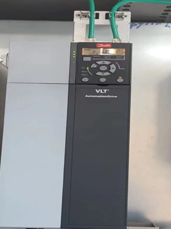
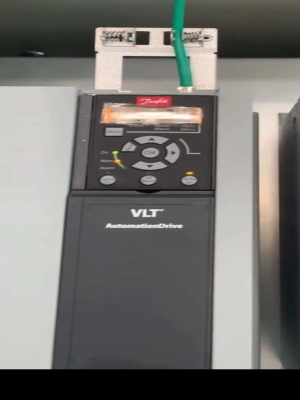
Inverter:FC360
2. Commissioning Software
PLC Software:TIA Portal V15(SIEMENS)、SMART V2.4
HMI Software:TIA Portal V15(SIEMENS)
Frequency converter and CPU communication method :PN communication Inverter commissioning software:VLT_MCT10_V5.21
3.Single-action commissioning of machine
1.1 Take-up power-on commissioning. (Generally factory energized before commissioning)
1.2 "Motor self-tuning" for cage, Taping unit and caterpiller motors. Set the following basic parameters to complete the self-tuning:
| 0-01 Language | English | English |
| 1-20 Motor power | KW | Input according to motor nameplate |
| 1-22 Motor voltage | V | Input according to motor nameplate |
| 1-23 Motor frequency | HZ | Input according to motor nameplate |
| 1-24 Motor current | A | Input according to motor nameplate |
| 1-25 Motor rated speed | RPM | Input according to motor nameplate |
| 1-39 Motor poles | Input according to motor nameplate | |
| 5-12 Terminal DI 1 digital input | No function | No function |
| 1-29 Automatic motor adjustment | Option 1, complete self-tuning | Option 1, complete self-tuning |
| 3-02 Minimum reference value | 0 | 0 |
| 3-03 Maximum reference value | HZ | Input according to motor nameplate |
- Single-action idling of each body. Local control inverter open loop operation, monitor whether 16_67 encoder direction is positive or not, otherwise the encoder direction is opposite to the motor direction.
Change the encoder direction: 1. Swap the encoder signal input A and signal B when the inverter is powered off. 2. Adjust parameter 5_71 encoder direction.
4.Inverter parameter setting
Inverter parameters are set with reference to the following table
| Cage | Caterpiller | Taping unit(n) | |||||
| 1-00 | 1 | 1 | 1 | ||||
| 1-01 | 1 | 1 | 1 | ||||
| 1-20 | Input according to motor nameplate | ||||||
| 1-22 | Input according to motor nameplate | ||||||
| 1-23 | Input according to motor nameplate | ||||||
| 1-24 | Input according to motor nameplate | ||||||
| 1-25 | Input according to motor nameplate | ||||||
| 1-82 | 0.5 | 0.5 | 0.5 | ||||
| 3-00 | 1 | 1 | 1 | ||||
| 3-02 | 0 | 0 | 0 | ||||
| 3-03 | Calculation according to the drawing drive | ||||||
| 3-41 | 1.0 | 1.0 | 1.0 | ||||
| 3-42 | 1.0 | 1.0 | 1.0 | ||||
| 4-10 | 2 | 2 | 2 | ||||
| 4-20 | 0 | 0 | 0 | ||||
| 5-12 | 2 | 2 | 2 | ||||
| 5-40 | 5 | 5 | 5 | ||||
| 5-42 | 60 | 60 | 60 | ||||
| 8-04 | 5 | 5 | 5 | ||||
| 8-10 | 0 | 0 | 0 | ||||
| 915.0 | Control word | ||||||
| 915.1 | Reference word | ||||||
| 915.2 | Design Needs | ||||||
| 916.0 | Status word | ||||||
| 916.1 | Feedback value | ||||||
| 916.2 | Motor current |
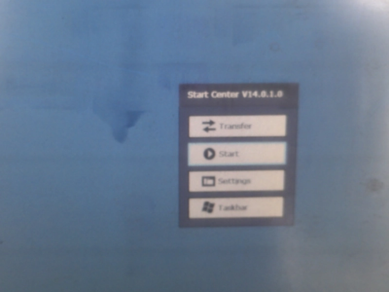
5.HMI and PLC program
5.1 IP address setting of the HMI: Click "settings" to enter the settings:
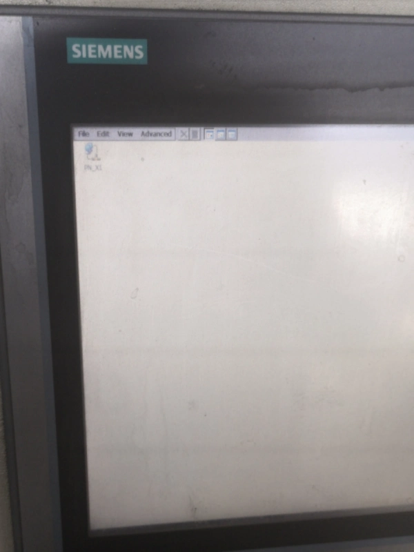
5.1.1 Select PN/IE, click "properties" to enter
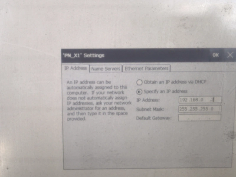
5.1.2 Setting the IP address 192.168.0.2 manually
5.2 HMI program download:Open the project, select HMI, and click Download The following screen appears:
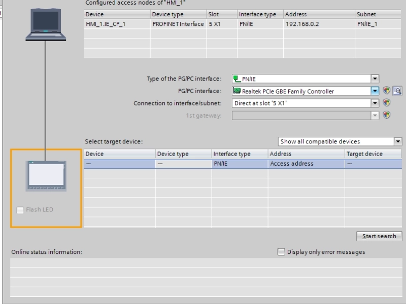
In the picture you will see 192.168.0.2,Then select and click load.
5.3 After downloading the program, observe whether all inverters and modules communicate normally.
Note: The communication interruption inverter will report W34.
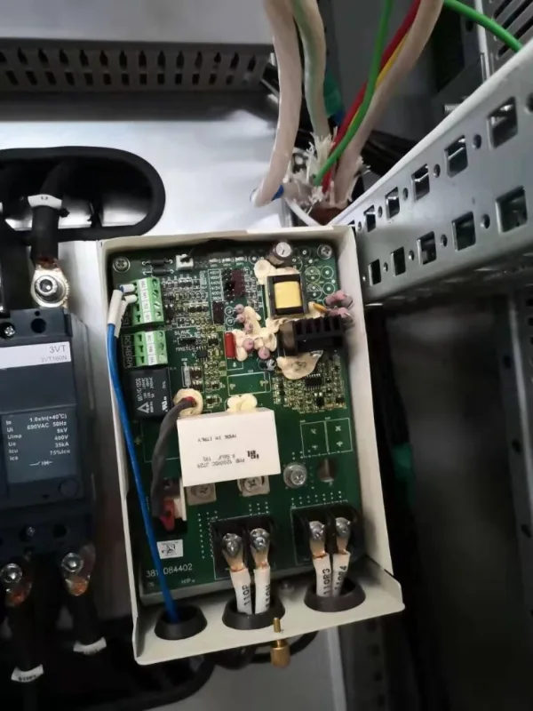
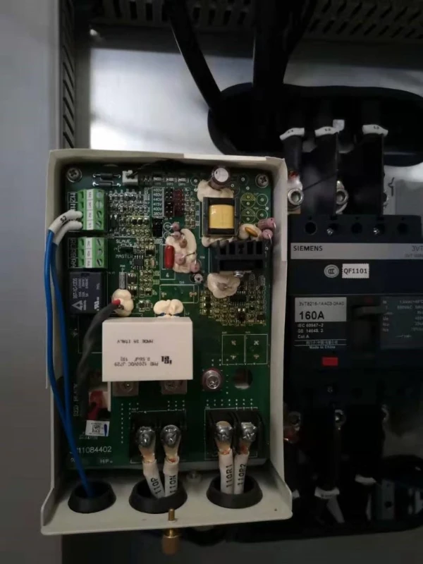
5.4 The brake unit dipswitch must be operated with power off!
6.Whole machine linkage
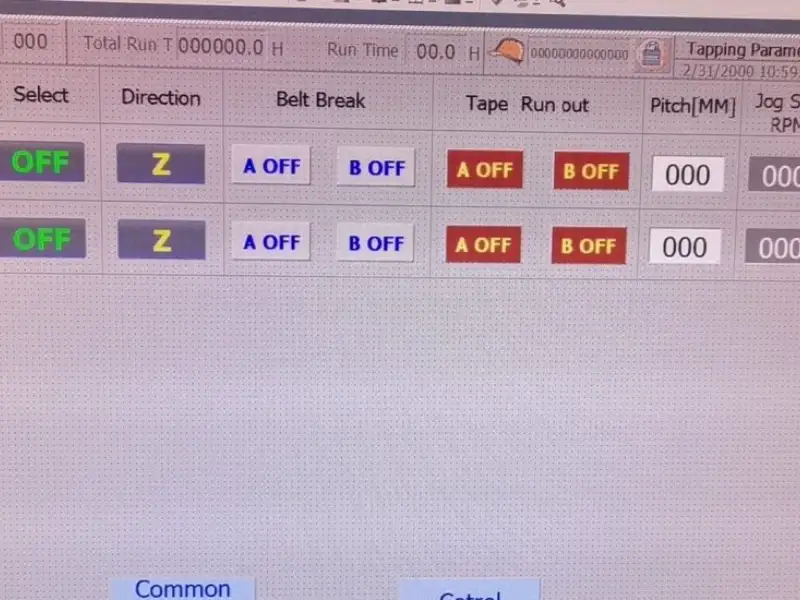
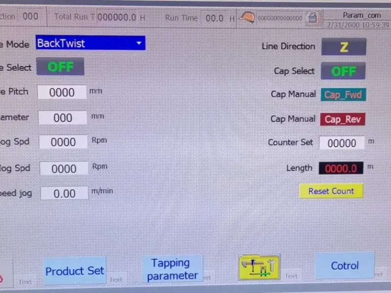
6.1 The following parameters must be set before the whole machine is linked.
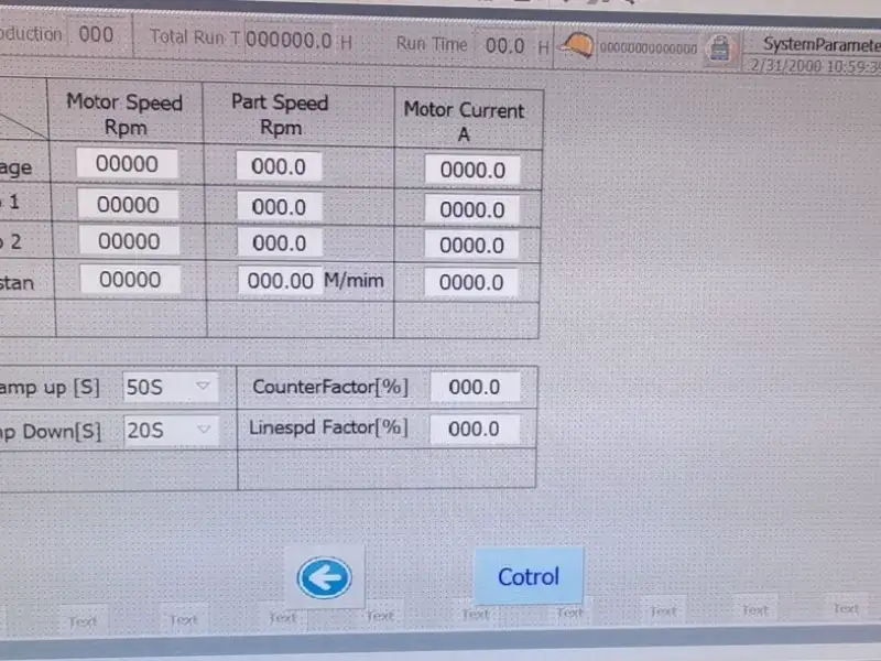
6.2 Start Caterpillar, cage, Taping unit test run in turn, stop to test switching direction
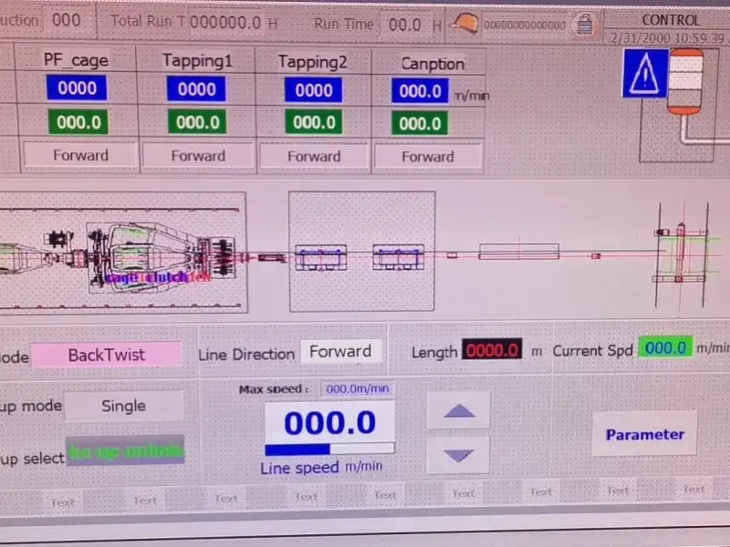
6.2.1 The machine is observed from low speed to high speed to see if the motor speed and current of each part are normal.
6.2.2 No-load should be fault-free continuous operation for more than 2 hours before product cable.
6.2.3Confirm whether the actual pitch is the same as the interface setting pitch, and correct if different.